Mastertemp 400 Manual: A Comprehensive Guide
This manual details the Pentair Mastertemp 400’s features, installation, operation, and maintenance․ It covers safety precautions, parts diagrams, and troubleshooting steps for optimal performance․
Welcome to the world of efficient and reliable pool heating with the Pentair Mastertemp 400! This heater is engineered to provide consistent warmth and enhance your swimming experience․ This manual serves as your comprehensive guide, detailing everything you need to know about your new heating system․
The Mastertemp 400 boasts a compact design and powerful performance, delivering 400 BTU/hr․ It’s designed for easy installation and operation, ensuring years of trouble-free enjoyment․ Understanding its features and following the guidelines within this manual will maximize its lifespan and efficiency․ We’ll cover safety, installation, operation, maintenance, and troubleshooting to ensure a seamless experience․
Understanding the Mastertemp 400 Features
The Mastertemp 400 is packed with features designed for optimal performance and user convenience․ Key highlights include its 400 BTU/hr heating capacity, suitable for various pool sizes․ The unit offers a 270-degree discharge rotation for flexible venting options, and operates with vent gas temperatures under 400°F․
A compact control system simplifies operation, while the thermal regulator ensures consistent water temperature․ Heavy-duty models are available for demanding applications․ Its sealed-seam vent pipe compatibility enhances safety and efficiency․ This heater is built for durability and reliability, providing years of comfortable swimming․ Explore these features to unlock the full potential of your Mastertemp 400!
Safety Precautions
Prioritizing safety is crucial when installing and operating your Mastertemp 400․ Always adhere to general safety guidelines, including proper grounding and avoiding flammable materials․ Outdoor use requires extra caution, protecting the unit from the elements and ensuring adequate ventilation․
Electrical safety is paramount; never operate with damaged cords or in wet conditions․ Follow installation instructions meticulously, verifying vent pipe specifications for safe exhaust․ Be aware of potential risks, and never attempt repairs without professional assistance․ Ignoring these precautions could lead to hazards․ Always consult the full manual for detailed safety information․
General Safety Guidelines
Before operating the Mastertemp 400, thoroughly read and understand this manual․ Ensure proper grounding to prevent electrical shock․ Keep the heater area clear of combustible materials like paper and gasoline․ Never operate the unit if it shows any signs of damage․ Regularly inspect the heater and vent pipe for corrosion or leaks․
Always disconnect power before performing maintenance․ Do not bypass safety controls or alter the unit’s design․ Qualified personnel should handle all repairs․ Keep children and pets away from the heater during operation․ Adherence to these guidelines ensures safe and reliable performance, preventing potential hazards․
Outdoor Use Safety
When installing the Mastertemp 400 outdoors, protect it from the elements․ Ensure adequate ventilation to prevent carbon monoxide buildup․ The unit must be shielded from direct rainfall and snow accumulation, potentially causing damage․ Regularly inspect for water ingress and corrosion․ Secure the heater to a stable, level surface to prevent tipping․
Maintain clear access for maintenance and inspection․ Be mindful of wind conditions, which can affect combustion efficiency․ Avoid operating the heater in excessively humid environments․ Proper outdoor installation and maintenance are crucial for safe and reliable operation, extending the unit’s lifespan․
Electrical Safety
The Mastertemp 400 requires a dedicated electrical circuit․ Ensure the voltage and amperage match the heater’s specifications․ Always disconnect power before performing any maintenance or inspection․ Ground the heater properly to prevent electrical shock․ Never use extension cords or adapters; install a dedicated outlet․
Inspect wiring for damage regularly and replace if necessary․ Avoid operating the heater with wet hands or in wet conditions․ A qualified electrician should handle all electrical connections․ Adhering to these electrical safety guidelines is vital for preventing hazards and ensuring the longevity of your Mastertemp 400․
Installation Guide
Proper installation is crucial for the Mastertemp 400’s performance and safety․ Begin by verifying heater identification information against your purchase․ Installation requires adequate ventilation and adherence to local codes․ Ensure sufficient clearance around the unit for service access․ The vent pipe specifications must be strictly followed, utilizing sealed-seam construction rated for Category III appliances and temperatures under 400°F․
Carefully review the provided diagrams and instructions․ Incorrect installation can void the warranty and create hazardous conditions․ Professional installation is recommended for those unfamiliar with gas and electrical systems․
Heater Identification Information
Locate the heater’s nameplate, typically found on the unit’s exterior․ This plate contains vital information, including the model number (Mastertemp 400), serial number, BTU/hr rating (400 BTU/hr), and voltage requirements․ Record this information for future reference, warranty claims, and parts ordering․ Verify that the heater matches your order and that all components are present․
The nameplate also indicates gas type compatibility․ Ensure your gas supply matches the heater’s specifications․ Refer to the exploded view diagram for component identification․ This information is essential for proper installation and maintenance․
Installation Requirements
Installation must adhere to local codes and regulations․ A qualified technician should perform the installation․ Ensure adequate ventilation and clearance around the heater, as specified in the manual․ The unit requires a level, stable surface capable of supporting its weight․ Verify proper gas supply connection and leak testing before operation․
Electrical connections must comply with national and local electrical codes․ Grounding is essential for safety․ Consider the vent pipe specifications for proper exhaust․ The heater must be installed in a dry, protected location, shielded from the elements․
Vent Pipe Specifications
The vent pipe must be sealed-seam construction, suitable for Category III appliances․ It should withstand operating temperatures below 400°F (204°C)․ Use only approved venting materials, like polypropylene or PVC, as outlined in the manual․ Ensure proper slope for condensate drainage, preventing water accumulation and corrosion․
Maintain specified vent pipe lengths and avoid excessive bends, which can restrict airflow․ Securely support the vent pipe to prevent sagging or movement․ Inspect the vent pipe regularly for damage or obstructions․ Proper venting is crucial for safe and efficient heater operation, preventing carbon monoxide buildup․
Operation Instructions
Before initial startup, verify proper installation and ensure all connections are secure․ The control panel offers intuitive operation for adjusting temperature and monitoring performance․ Familiarize yourself with the control panel’s functions before use․ To initiate heating, set the desired temperature using the control panel buttons․
The Mastertemp 400 features a compact control system for precise temperature regulation․ Monitor the heater’s status indicators for any error messages․ Regularly check the water flow rate to ensure optimal heat transfer․ Avoid operating the heater outside its specified parameters․
Initial Startup Procedure
Prior to the first use, thoroughly inspect the heater and plumbing connections for leaks․ Ensure the gas supply is turned on and verify proper ventilation․ Slowly open the water supply valve to fill the heater and associated piping․ Purge any air from the system before activating the heater․
Turn on the power supply to the control panel․ Follow the control panel prompts to initiate the startup sequence․ Monitor the heater’s operation during the initial warm-up period․ Confirm that the burner ignites and the water begins to heat․ If issues arise, consult the troubleshooting section․

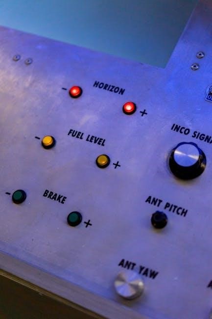
Control Panel Overview
The Mastertemp 400’s control panel features a user-friendly interface for managing heater functions․ Key elements include a digital display showing water temperature, mode selection buttons (Heat, Cool, Auto), and temperature adjustment controls․ A status indicator displays the heater’s operational state – active, standby, or error․
The compact control system allows for precise temperature settings and monitoring․ Diagnostic codes are displayed in case of malfunctions, aiding in troubleshooting․ Familiarize yourself with the panel’s layout and functions before operation․ Refer to the detailed diagrams for specific button assignments and display interpretations․
Temperature Adjustment
Adjusting the Mastertemp 400’s temperature is straightforward using the control panel’s dedicated buttons․ Press the “+” or “-” buttons to increase or decrease the desired water temperature, displayed digitally․ The heater responds to these adjustments, maintaining the setpoint․ Ensure the selected temperature aligns with your pool or spa’s requirements and safety guidelines․
The thermal regulator functionality ensures stable and efficient heating․ Avoid drastic temperature changes, as they can impact performance․ Monitor the display to confirm the set temperature and the actual water temperature․ Fine-tune adjustments as needed for optimal comfort and energy conservation․
Maintenance and Troubleshooting
Regular maintenance extends the Mastertemp 400’s lifespan and ensures efficient operation․ Inspect the unit for debris, corrosion, and leaks․ Clean the burner assembly and check vent pipe connections annually․ Troubleshooting common issues like no heat often involves verifying gas supply and electrical connections․ Error codes displayed on the control panel provide diagnostic clues․
Winterization is crucial in colder climates․ Drain all water from the heater and protect it from freezing temperatures․ Consult the manual for specific winterization procedures․ If issues persist, contact a qualified technician․ Proper maintenance prevents costly repairs and maximizes performance․
Regular Maintenance Tasks

Consistent upkeep is vital for your Mastertemp 400’s longevity․ Annually, inspect the heater for corrosion, debris accumulation, and any signs of water leakage around connections․ Thoroughly clean the burner assembly to ensure optimal combustion․ Verify the integrity of the vent pipe, checking for secure connections and proper sealing․
Periodically, examine the gas valve and control panel for any irregularities․ Clean the exterior surfaces with a mild detergent․ Regularly check and clear any obstructions around the air intake and exhaust vents․ Following these tasks will maintain peak efficiency and prevent potential issues․
Troubleshooting Common Issues
If your Mastertemp 400 fails to ignite, first check the gas supply and ensure it’s fully open․ Verify the pilot light is lit, or attempt to relight it following the startup procedure․ If the heater cycles on and off frequently, inspect the water flow rate and filter for obstructions․ A low water flow can trigger the high-limit switch․
For error codes displayed on the control panel, consult the error code list in this manual․ Unusual noises may indicate a problem with the blower motor or gas valve․ If issues persist, contact a qualified technician for assistance; do not attempt complex repairs yourself․
Winterization Procedures
Before freezing temperatures arrive, properly winterize your Mastertemp 400 to prevent damage․ Begin by turning off the gas supply and electrical power to the heater․ Drain all water from the heater, plumbing lines, and filter system using the drain plugs provided․ Remove any debris from the vent pipe to ensure proper airflow when restarting in the spring․
Consider using a non-toxic RV antifreeze in the plumbing lines to further protect against freezing․ Cover the heater with a protective cover to shield it from the elements․ Regularly inspect the unit throughout the winter for any signs of damage or leaks․
Parts Diagram and Replacement
This section provides a detailed overview of the Mastertemp 400’s key components․ An exploded view diagram illustrates each part’s location and relationship to the overall system․ Identifying these components is crucial for efficient maintenance and repairs․ When ordering replacement parts, always refer to the part number listed in the diagram to ensure compatibility․
Genuine Pentair replacement parts are recommended for optimal performance and longevity․ Contact authorized Pentair distributors or visit the Pentair website to locate and purchase the necessary parts․ Always disconnect the power supply before attempting any repairs or replacements․
Identifying Key Components
The Mastertemp 400 consists of several vital components․ These include the burner assembly, heat exchanger, gas valve, control panel, and various sensors․ Understanding the function of each part is essential for troubleshooting and maintenance․ The burner assembly ignites the gas to generate heat, while the heat exchanger transfers that heat to the water․
The gas valve regulates gas flow, and the control panel manages the heater’s operation․ Sensors monitor temperature and pressure, ensuring safe and efficient performance․ Refer to the exploded view diagram for precise locations and part numbers․ Proper identification prevents incorrect part replacement․
Ordering Replacement Parts
To order replacement parts for your Mastertemp 400, accurate identification is crucial․ Refer to the parts diagram and note the specific part number required․ Contact an authorized Pentair distributor or visit the Pentair website for ordering․ Provide the heater’s model number and serial number for verification․
Ensure the replacement part is compatible with your specific Mastertemp 400 configuration․ Incorrect parts can lead to malfunction or safety hazards․ Distributors can assist in identifying the correct component․ Always follow safety guidelines when installing replacement parts, and consider professional assistance if needed․

Exploded View Diagram
The exploded view diagram provides a detailed visual representation of the Mastertemp 400’s assembly․ It illustrates each component’s location and relationship to other parts, aiding in identification during maintenance or repair․ This diagram is essential for understanding the heater’s internal structure․
Carefully study the diagram before disassembling any part of the heater․ Note the orientation of components and the order of assembly․ The diagram typically includes a parts list with corresponding reference numbers․ Use this list to accurately identify and order replacement parts when needed․ Proper use of the diagram ensures efficient and safe repairs․
Technical Specifications
The Mastertemp 400 boasts specific performance characteristics crucial for optimal operation․ Its BTU/hr rating is 400, indicating its heating capacity․ Vent gas temperature limits are capped at 400°F (204°C), ensuring safe exhaust management․ A key feature is its 270-degree discharge rotation capability, offering flexible venting options․

These specifications are vital for proper installation and troubleshooting․ Adhering to these limits prevents overheating and ensures efficient performance․ Understanding these parameters allows for informed decisions regarding venting configurations and operational adjustments․ Always refer to these specifications when servicing or replacing components․
BTU/hr Ratings (400 BTU/hr)
The Mastertemp 400 is specifically rated at 400,000 BTU/hr, defining its heating power output․ This rating signifies the amount of heat the unit generates per hour, crucial for determining its suitability for pool or spa volume․ Understanding this BTU/hr value is essential for efficient heating and maintaining desired water temperatures․
Properly matching the heater’s BTU rating to the pool’s size minimizes energy consumption and maximizes heating performance․ A 400,000 BTU/hr rating is ideal for smaller pools or spas, providing rapid and consistent heating․ Always verify this rating during installation and when assessing heating needs․
Vent Gas Temperature Limits (400°F)
The Mastertemp 400 operates with a maximum vent gas temperature limit of 400°F (204°C)․ Maintaining this limit is critical for safe and efficient operation, preventing potential damage to the venting system and surrounding components․ Exceeding this temperature poses a fire hazard and voids the warranty․
Regular inspection of the vent pipe is crucial to ensure proper airflow and prevent overheating․ The vent pipe must be constructed of materials rated for these temperatures, such as those approved for Category III appliances․ Monitoring vent gas temperatures helps ensure compliance with safety standards and prolongs the heater’s lifespan․
Discharge Rotation Capabilities (270-degree)
The Mastertemp 400 heater boasts a 270-degree discharge rotation capability, offering significant flexibility during installation․ This feature allows for adaptable venting configurations, accommodating various structural layouts and minimizing installation complexities․ Proper rotation ensures optimal exhaust flow and prevents back pressure․
Carefully consider the available space and venting pathway when adjusting the discharge․ Ensure the vent pipe maintains a consistent slope and avoids sharp bends․ Correct positioning maximizes efficiency and minimizes potential issues․ Always adhere to local codes and regulations regarding venting installations․
Warranty Information
Your Pentair Mastertemp 400 heater is covered by a limited warranty, protecting against defects in materials and workmanship․ Coverage details, including the warranty period, are outlined in the separate warranty document included with your purchase․ To initiate a claim, you must provide proof of purchase and a detailed description of the issue․
The warranty does not cover damage resulting from improper installation, misuse, neglect, or unauthorized modifications․ Certain limitations and exclusions apply, such as routine maintenance and consumable parts․ Contact Pentair customer support for assistance with warranty claims and to understand your rights․
Coverage Details
The Pentair Mastertemp 400 warranty provides coverage for manufacturing defects in materials and workmanship for a specified period, typically one to five years depending on the component․ Heat exchangers often have extended warranties, reflecting their critical function․ This warranty covers the cost of replacement parts and labor, subject to verification of the defect․
Coverage begins on the date of original purchase, and requires the product to be installed and operated according to the instructions․ The warranty is non-transferable and applies only to the original purchaser․ Keep your proof of purchase safe to facilitate any potential claims․
Claim Process
To initiate a warranty claim for your Mastertemp 400, first contact a Pentair authorized service technician for diagnosis and verification of the defect․ Do not attempt to repair the unit yourself, as this may void the warranty․ Obtain a written report from the technician detailing the issue and recommended solution․
Submit the technician’s report, along with proof of purchase and a claim form (available from Pentair), to the designated warranty claims department․ Pentair will review the claim and, if approved, authorize the repair or replacement of the defective part․ Ensure all documentation is complete for swift processing․
Limitations and Exclusions
This warranty does not cover damage resulting from improper installation, operation, or maintenance, including failure to follow the instructions in this manual․ It excludes issues caused by freezing, corrosion, scale buildup, or the use of unapproved chemicals․ Damage from acts of God, such as floods or lightning, is also not covered․
Furthermore, the warranty is voided by unauthorized repairs, modifications, or the use of non-genuine Pentair replacement parts․ Incidental and consequential damages are specifically excluded․ This warranty applies only to the original purchaser and is non-transferable․
Advanced Settings and Features
The Mastertemp 400 incorporates a sophisticated thermal regulator, optimizing heat output and efficiency based on demand․ Its compact control system allows for precise temperature adjustments and monitoring․ Heavy-duty models are designed for increased durability and extended lifespan, handling higher usage volumes․
The 270-degree discharge rotation provides flexible venting options, adapting to various installation environments․ Operating within the 400°F vent gas temperature limit ensures safe and efficient performance; Advanced diagnostics aid in troubleshooting, simplifying maintenance procedures․
Thermal Regulator Functionality
The Mastertemp 400’s thermal regulator dynamically adjusts heat output, responding to pool or spa water temperature fluctuations․ This intelligent system maximizes energy efficiency by preventing overheating and maintaining consistent warmth․ It optimizes performance across varying demand levels, ensuring comfortable water temperatures․
The regulator’s precise control minimizes temperature swings, enhancing user experience․ It operates automatically, requiring no manual intervention for optimal heating․ This feature contributes to lower operating costs and prolonged heater lifespan․ Regular monitoring of the regulator’s performance is recommended for continued efficiency․
Compact Control System
The Mastertemp 400 features a streamlined, user-friendly control system designed for intuitive operation․ This integrated system manages all heater functions, including temperature settings, diagnostics, and safety features․ Its compact design simplifies installation and minimizes space requirements․ The control panel provides clear, concise information at a glance․
Users can easily adjust desired water temperatures and monitor heater status․ The system incorporates advanced algorithms for precise temperature control and efficient energy usage․ Diagnostic capabilities aid in troubleshooting potential issues․ Regularly reviewing the control system’s settings ensures optimal performance and longevity․

Heavy Duty Model Considerations
The Mastertemp 400 Heavy Duty model is engineered for demanding applications and extended use․ This robust version incorporates reinforced components and enhanced durability․ Considerations for installation include ensuring adequate ventilation and structural support․ Regular inspection of all connections and components is crucial for maintaining peak performance․
Due to increased power and operational demands, the Heavy Duty model may require dedicated electrical circuits․ Proper grounding is essential for safety․ Monitoring vent gas temperatures, staying below the 400°F limit, is vital․ Adhering to recommended maintenance schedules will maximize the lifespan of this powerful heater․

Frequently Asked Questions (FAQ)
Q: Why is my Mastertemp 400 not heating? A: Check the gas supply, power connection, and control panel settings․ Q: What does the error code mean? A: Refer to the troubleshooting section for code definitions․ Q: How often should I inspect the vent pipe? A: Annually, or after any relocation or maintenance․ Q: Can I use any type of vent pipe? A: No, use sealed-seam pipes rated for Category III appliances․

Q: What is the maximum vent gas temperature? A: 400°F․ Q: Where can I find replacement parts? A: Contact a Pentair dealer or visit their website․ Q: Is professional installation required? A: Recommended for optimal safety and performance․
Common User Queries
Q: My heater won’t start – what should I do? A: Verify the gas supply is on, the power switch is engaged, and the control panel displays no error codes․ Q: How do I reset the heater after a lockout? A: Consult the operation instructions for the specific reset procedure․ Q: Is the heater compatible with salt chlorine generators? A: Yes, but ensure proper grounding and compatibility․

Q: What causes condensation on the vent pipe? A: Normal during initial operation, but excessive condensation may indicate a venting issue․ Q: Can I install the heater myself? A: Professional installation is strongly recommended for safety and warranty validity․
Troubleshooting Tips
If the heater fails to ignite, check the gas valve and pilot light (if applicable)․ For error codes, consult the control panel section of this manual for specific meanings and solutions․ Low water flow can trigger a safety shutdown; verify adequate water levels and pump operation․ High vent temperatures may indicate a blockage – inspect the vent pipe․
If you suspect a gas leak, immediately shut off the gas supply and contact a qualified technician․ Frozen pipes require careful thawing; avoid direct heat․ Always disconnect power before performing any maintenance․
Contact Information
For technical support and warranty claims, please contact Pentair’s dedicated customer service team․ Our helpline is available Monday-Friday, 8 AM to 5 PM EST, at 1-800-8PENTAIR (1-800-873-6824)․ You can also reach us via email at support@pentair․com․ Visit our website at www․pentair․com for frequently asked questions, downloadable resources, and online support options․
For parts inquiries, please have your heater’s model and serial number readily available․ Local Pentair distributors can also provide assistance and service․ Ensure you have your proof of purchase when contacting us regarding warranty issues;